Next: Communication-sensitive binding
Up: Interconnect-aware binding
Previous: Interconnect-aware binding
For a CDFG node (an operation in the behavior), we define its
behavioral neighbors to be the other CDFG nodes which
have data communication with it in the CDFG. After high-level
synthesis, CDFG nodes and edges (variables) are mapped to RTL DPUs
like functional units and registers through the binding process. A
DPU,'s RTL neighbors are defined as the other DPUs that
have data communication with it. After DPUs are floorplanned, we
define a DPU's physical neighbors as the DPUs adjacent to
it in the floorplan. The data communication cost will be reduced
if DPUs, which exchange data, are placed close to each other in
the floorplan, i.e., RTL neighbors are made physical neighbors. A
data transfer is called  if it happens between two
neighboring operations or DPUs. It is obvious that behavioral
locality, RTL locality and physical locality are different.
To reduce the communication cost, some researchers have proposed
techniques to localize data transfers at different
levels [2,60].
In [60], an algorithmic transformation
is proposed to localize data transfers in VLSI array processors.
In [2], behavioral partitioning is advocated for
exploiting behavioral locality and ensuring RTL locality after
binding. These methods are only effective for highly regular
signal processing behaviors. Besides, they do not distinguish
between RTL locality and physical locality. We use a
neighborhood-sensitive binding technique which does not rely on
the behavior and effectively preserves/creates physical locality
in circuits.
To localize data transfers at the physical level, we should ensure
that as many RTL neighbors as possible are also physical
neighbors, especially those that conduct high unit-length switched
capacitance data exchange with each other. On the other hand, the
physical neighborhood capacity of a DPU is limited, and is related
to its geometry. We define the neighborhood crowd of a
DPU,
if it happens between two
neighboring operations or DPUs. It is obvious that behavioral
locality, RTL locality and physical locality are different.
To reduce the communication cost, some researchers have proposed
techniques to localize data transfers at different
levels [2,60].
In [60], an algorithmic transformation
is proposed to localize data transfers in VLSI array processors.
In [2], behavioral partitioning is advocated for
exploiting behavioral locality and ensuring RTL locality after
binding. These methods are only effective for highly regular
signal processing behaviors. Besides, they do not distinguish
between RTL locality and physical locality. We use a
neighborhood-sensitive binding technique which does not rely on
the behavior and effectively preserves/creates physical locality
in circuits.
To localize data transfers at the physical level, we should ensure
that as many RTL neighbors as possible are also physical
neighbors, especially those that conduct high unit-length switched
capacitance data exchange with each other. On the other hand, the
physical neighborhood capacity of a DPU is limited, and is related
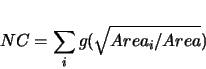
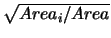
to its geometry. We define the neighborhood crowd of a
DPU,  , as,
, as,
where  is
is  if
if  ,
,  if
if  ,
,  is its area,
and
is its area,
and  is the area of its
  th RTL neighbor. The area
information is obtained from the RTL design library. The
definition of is based on the following observations. First,
the capacity of a DPU to have physical neighbors is decided by its
width and height. Second, it can have more small physical
neighbors than big ones. These two observations lead to the use of
th RTL neighbor. The area
information is obtained from the RTL design library. The
definition of is based on the following observations. First,
the capacity of a DPU to have physical neighbors is decided by its
width and height. Second, it can have more small physical
neighbors than big ones. These two observations lead to the use of
 as the argument for
function
as the argument for
function  . Another observation is that when a smaller DPU has a
larger physical neighbor, that neighbor tends to just dominate one
side of the smaller unit. This leads to the choice for .
As a DPU's gets larger, it becomes more difficult to make all
its RTL neighbors its physical neighbors as well. In the iterative
improvement algorithm we employ for high-level synthesis, various
moves are defined. Two binding moves that affect are DPU
sharing and splitting (See Section VI for details). When making
such moves, in addition to evaluating the power/area gains in the
DPUs, we also use an -based factor which reflects how much the
average DPU changes with the move. Moreover, if such a move
increases the of the new DPU beyond a certain threshold, it
is simply rejected. This approach not only reduces power, but also
area due to an improved floorplan.
There are two parameters for the use of . First, the threshold
for to reject a move. When for a DPU is above the
threshold, the DPU said to be overcrowded. We intuitively set the
threshold as 4.0 since a DPU can have four physical neighbors of
its own size. We observed that a very few moves are rejected
because of overcrowding a DPU during iterative improvement.
Second, when we combine the gain and power gain to evaluate a
move, there is a problem of scale. We estimate the power impact of
a unit increase as that by a data transfer with
typical(statistical mean) unit-length switched capacitance and 1.5
times the square root of a typical DPU area.
. Another observation is that when a smaller DPU has a
larger physical neighbor, that neighbor tends to just dominate one
side of the smaller unit. This leads to the choice for .
As a DPU's gets larger, it becomes more difficult to make all
its RTL neighbors its physical neighbors as well. In the iterative
improvement algorithm we employ for high-level synthesis, various
moves are defined. Two binding moves that affect are DPU
sharing and splitting (See Section VI for details). When making
such moves, in addition to evaluating the power/area gains in the
DPUs, we also use an -based factor which reflects how much the
average DPU changes with the move. Moreover, if such a move
increases the of the new DPU beyond a certain threshold, it
is simply rejected. This approach not only reduces power, but also
area due to an improved floorplan.
There are two parameters for the use of . First, the threshold
for to reject a move. When for a DPU is above the
threshold, the DPU said to be overcrowded. We intuitively set the
threshold as 4.0 since a DPU can have four physical neighbors of
its own size. We observed that a very few moves are rejected
because of overcrowding a DPU during iterative improvement.
Second, when we combine the gain and power gain to evaluate a
move, there is a problem of scale. We estimate the power impact of
a unit increase as that by a data transfer with
typical(statistical mean) unit-length switched capacitance and 1.5
times the square root of a typical DPU area.
Next: Communication-sensitive binding
Up: Interconnect-aware binding
Previous: Interconnect-aware binding
Lin Zhong
2003-10-11